I built a Raspberry Pi Lego Robot, and a Python module which can control it. My goal was to use this robot to teach my children programming. By the end of this walkthrough, you'll see not only a robot you can control from a Raspberry Pi, but also a suite of code which will make programming it as easy as:
import arthurbot
myArthurBot=arthurbot.ArthurBot()
myArthurBot.forward(2)
myArthurBot.right(3)
myArthurBot.say("Say cheese!")
myArthurBot.takePhoto()
Without further ado, let's have a look at some video of it in action. In this video, you'll see it is capable of moving forward, backward, left, right and of speaking. I later added a camera and the ability to take photos.
On other pages:
You may also just want to download arthurbot.py , my Python module for controlling L293D-based robots from the Raspberry Pi.
On this page:
Here's the list of significant components. You don't have to use exactly these brands, you can adapt the design quite easily - including adapting it for studless construction. The only things you really must have are a Raspberry Pi, an L293 or L293D microchip (£3/US$5), two low-voltage DC motors and some caterpillar track.
Why did I pick the parts I picked? Show/Hide

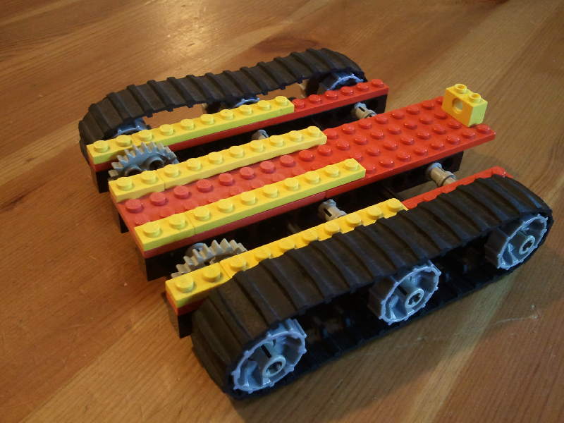
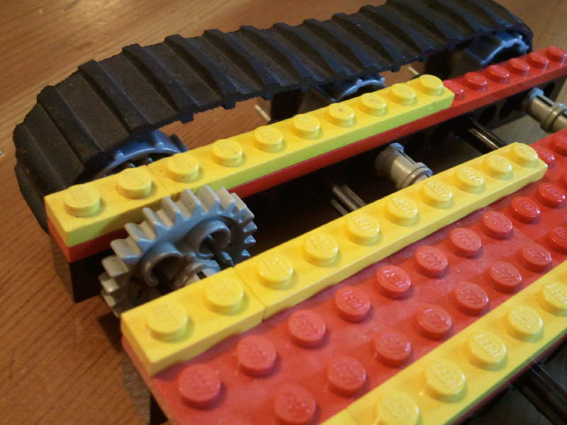
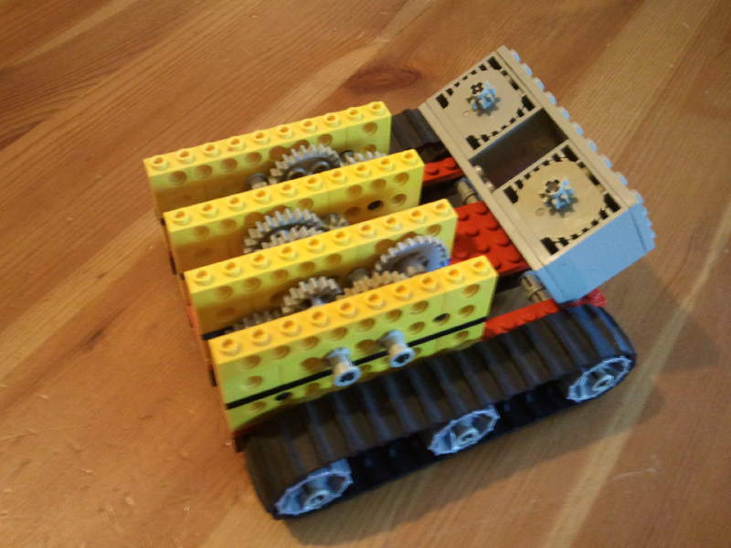
1. Here we're building the right-hand track; two long 16-stud beams and three 32007 sprockets. The front axle (leftmost in the photo) has a 16-toothed gear that fits inside the front sprocket to stop the sprocket spinning freely. A 24-toothed gear will connect to the gearbox when that's fitted above - the front axle will be the powered axle.
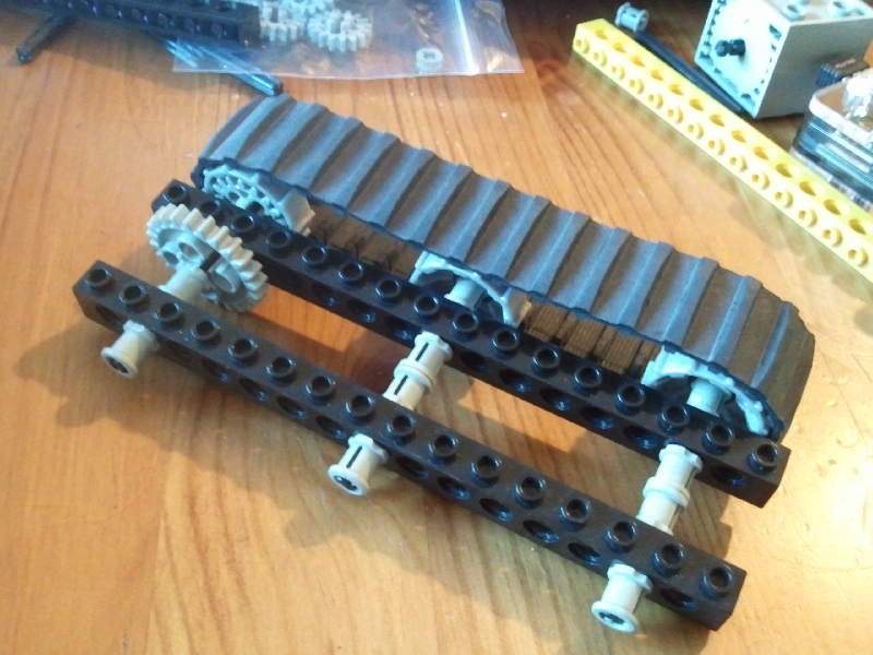
2. Ease the 680c01 tread onto the sprockets. Note again the 16-toothed gear that fits snugly inside the front sprocket (upper leftmost in this photo).
You don't strictly need the centre sprocket. It adds supporting strength to the tread but it's not a big deal.
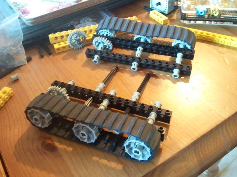
3. Build the left-hand track, which is the mirror image. Don't forget the 16-toothed gear inside the frontmost sprocket. I added two long axles through the centre of the track module, which will hold the two modules together.

4. Bushes hold everything in place.
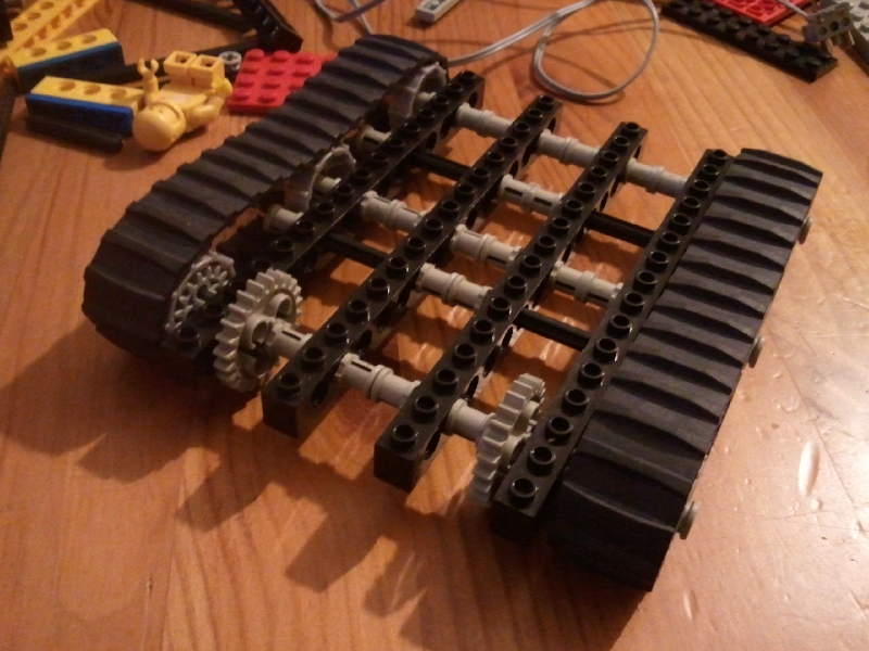
5. Note how the two tracks can turn independently of each other. This is vital for tank steering. To turn the robot, we will need one track to go forward whilst the other goes backward.
Notable parts for the track modules:
On the plus side, buying 680c01 tread is considerably cheaper than buying large numbers of 3873 link treads second-hand or buying set 9391 Tracked Crane new, but the down side is that you have a fixed size of track and thus a fixed size of robot. 3873 link treads give you much more flexibility to build larger robots - they also look much more professional. And the Tracked Crane set is only fifteen quid, for which you get quite a lot of caterpillar tread, a bargain if you're into modern studless Technic or if you're having trouble finding a good source for older tread.

6. DC motors spin very fast, but don't have much torque (turning force). Without a gearbox, the motors won't have enough force to move the tracks along the floor. Generally, a gearbox trades off speed for torque. A small gear turning a larger gear, makes the larger gear turn more slowly, but with more force. We use several of these small-to-large gearings to give us lots and lots of torque.
Note the 24-tooth gear and 8-tooth gear both mounted on the same axle on the right of this photo. The 8-tooth gear on this axle, will mesh with the 24-tooth gear on the front track sprocket.

7. There are gears on both sides of this studded wall, so that we can fit lots of gears into a small space without them locking up against each other.
The wall is 10 studs long, and you can use either an 8x1 + 2x1 beam, or a 6x1 + 4x1 beam. If you're using a 9-volt motor instead of a 4.5v motor, you might be able to get away with fewer gears, and thus a smaller gearbox and different beam sizes.
Note the Crown-toothed gear at the bottom of the photo. The teeth on this gear "turn a corner" so that they will mesh directly with the motor, when the motor is placed at right-angles to the other gears.
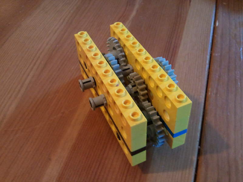
8. One completed gearbox. If you're using studless parts, your gearbox will probably look very different to this, but that doesn't matter; the point is, use a series of small-to-large gears to convert speed into torque.
Use your fingers to turn the crown gear - that's the one at the top of this photo. The lower 24-tooth gear - the one at the bottom of this photo - should turn slowly. If it doesn't, solve that problem before going any further. Most likely, something is jammed somewhere.
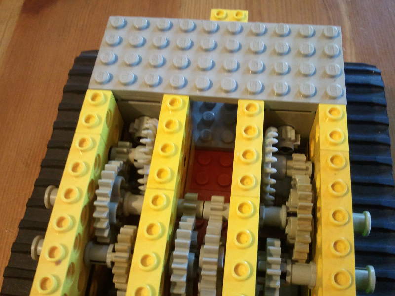
9. This studded design uses plates to mount studded beams on. The central plate overhangs by two studs at the rear, and 1x2 brick at the back will come in handy later, to hold a wiring block into place.
10. One of the downsides of using 1980s studded beams rather than the more modern studless beams, is that you have to use layers of thin plates to make the gears mesh properly when mounted vertically. With studless beams, you wouldn't need any of this nonsense - studless beams have their axle holes equidistant regardless of whether you mount them horizontally or vertically.
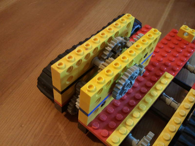
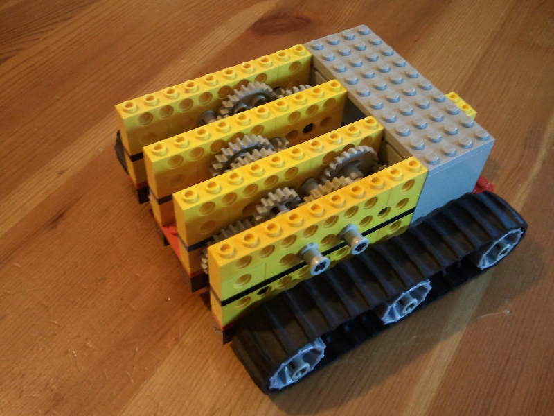
11. Here's the gearbox mounted on the tracked chassis. Note how the 24-tooth gear on the front axle fits onto an 8-toothed gear in the gearbox.
I've used blue and black stripes in the thin plates, so you can see which way round the gearbox fits onto the tracked chassis.

12. You'll need to build a mirror image of the gearbox for the left-hand track.

13. Now is an excellent time to check your gearing again. Lift the robot off the table (perhaps rest it on some basic bricks), so that the tracks no longer touch the ground. Then spin the crown gear with your fingers. The tread should move slowly. If it doesn't move, something is wrong or jammed. Remember, the gearboxes and tracks are meant to run independently of one another; spinning one crown gear should result in one and only one track moving. Make sure you test both tracks.
I strongly recommend you fix any gearing problems before you add the motors.
14. I've used old-style (well, not that old) 4.5v motors. These come in a couple of editions, which are almost identical, of which 6216m2 is the most commonly available second-hand.
Note that the older 1970s variant 6216m1 requires slightly different plugs which are much more difficult to get hold of (the 1980s/1990s m2 variant has a plug/socket with a middle pin, the 1970s m1 has no middle pin).
15. Hopefully you get an idea of how the 8-tooth gear on the motors, will mesh with the 24-tooth crown gear in the gearboxes.
You can, of course, use modern 9-volt motors, in which case you'll need more AA batteries (or a single 9v battery) and different gearing in your gearbox. Lego is all about trying things out.
16. Studded bottom-up construction here gives me a familiar flat surface to build upon using regular Lego Creator / City / Legoland / Minifig parts. But if you're a pure Technics gearhead, that's no advantage - and your studless construction will almost certainly be lighter in weight and thus require less torque to move around.
17. Here's a nice close-up of the gearboxes, showing how the motors' 8-tooth gears mesh into the 24-tooth crown gears.
This photo also shows how the gearboxes line up with less than a millimetre between the central gears. You really do need to use bushes to make sure the ends of the gear axles don't rub up against each other - remember they will be moving in opposite directions when turning left or right.
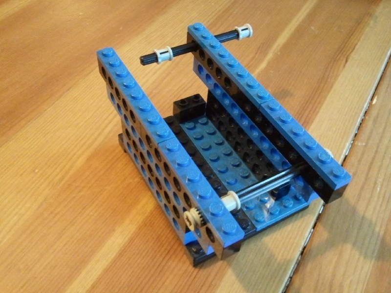
18. This channel will just hold the breadboard and the Raspberry Pi in place. There's no reason for it being built of studded Lego beams, it could just as well have been built using regular Lego 1-width bricks or studless beams.
The 10x2 plate on the right helps clamp down on the plugs going into the motors. If you're using the modern 9v system then you won't have the problem of loose plugs which plagued the 4.5v system.
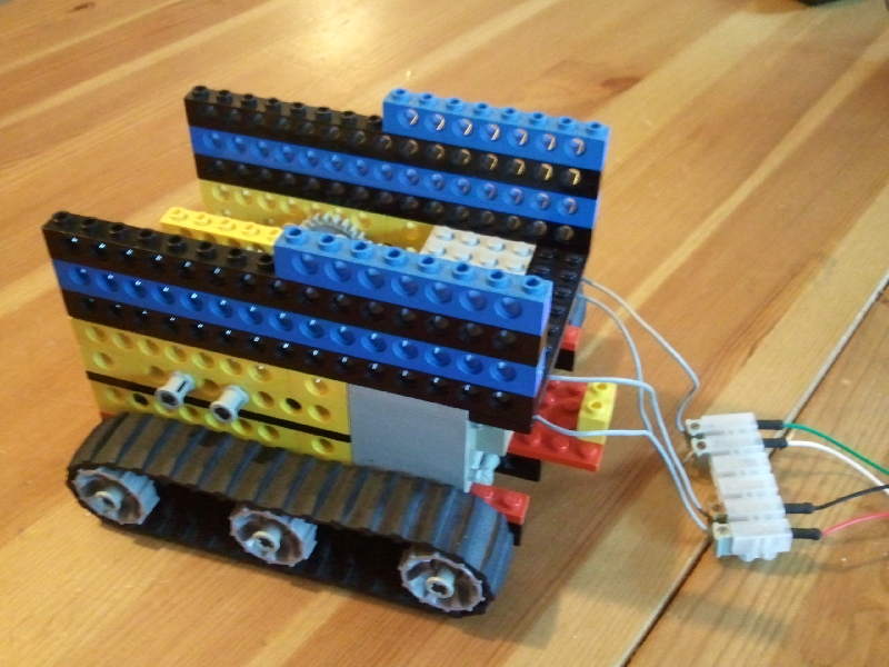
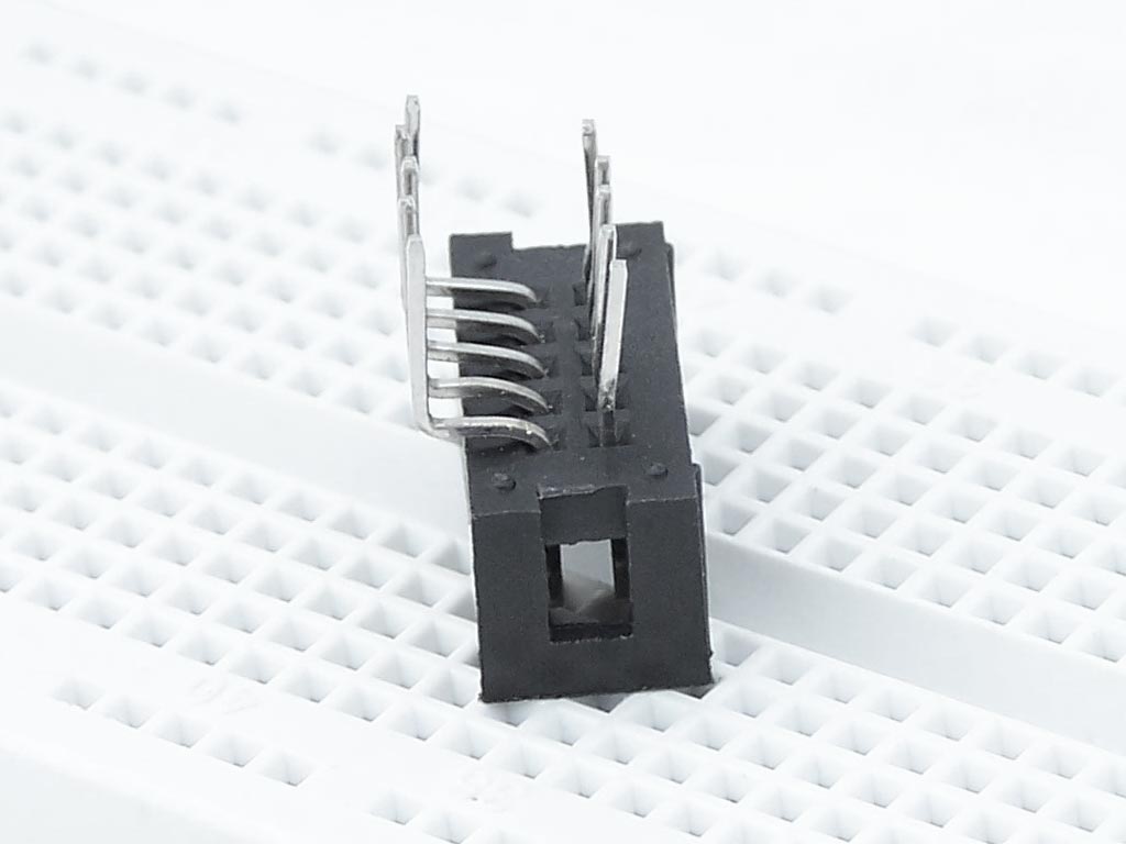
19. Here you can see I used a screw terminal block to interface between the 4.5v wiring system and the breadboard connector wires. I used one-prong connectors rather than the more common 2-prong or 3-prong 4.5v wires.
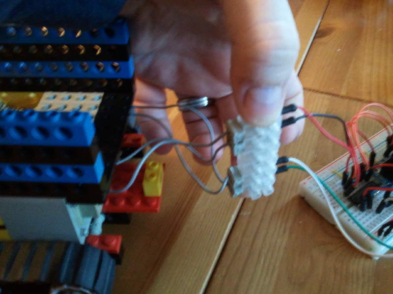
20. Most likely you are going to end up slicing up some wires and screwing it into a terminal block at some point, especially if you're using the 9v brick-type connectors.
Problems at this point will come down to two things:
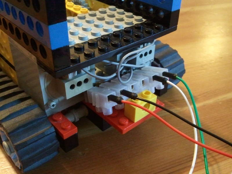
21. So that's what that little 2x1x1 brick was for. Holds the terminal block quite nicely.
I strongly recommend that you test your tracks, gearbox and motors now by simply plugging in the motors directly to the batteries. Swap the negative and positive, and the tracks should run in the opposite direction.
It's okay to run motors at one or two volts more than they are rated for, for a few seconds, but avoid doing it for prolonged periods.
Find your gearing or power problems now before you add the complexity of a breadboard circuit and a computer.
22. Here's the breadboard sitting in it's little channel. I used a half-size breadboard. There's room for a full-length breadboard if that's what you've got handy.
We'll go through the breadboard wiring in the next section, don't worry about it for now.

23. This is where using a Pibow case comes in handy. The Pibow has mounting holes on the base which are compatible with Lego. You can use two 2x2 plates and one 4x2 plate to mount it onto a 10x6 plate. I also used two 2x2 smooth tiles to give it more stability.
The plastic bolts hang down a little, like little feet, so if you want to use a base plate larger than 10x6, you'll need to use full-size bricks as shown at the top of this photo.

24. And there you go. I was concerned that the SD card poked out a little too much for a physical project such as this, and would be vulnerable. So I switched the SD card for an Adafruit 966 low-profile Micro SD adapter.
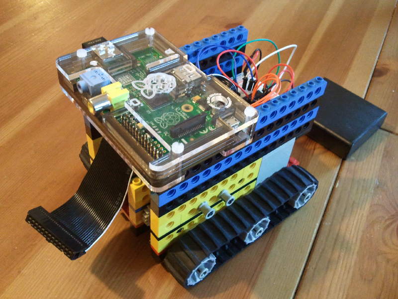
25. The Raspberry Pi mounted onto the robot using the Pibow case. Note how the Modela variant of the Pibow leaves the GPIO pins completely exposed, making it very easy to attach and detach the GPIO ribbon.
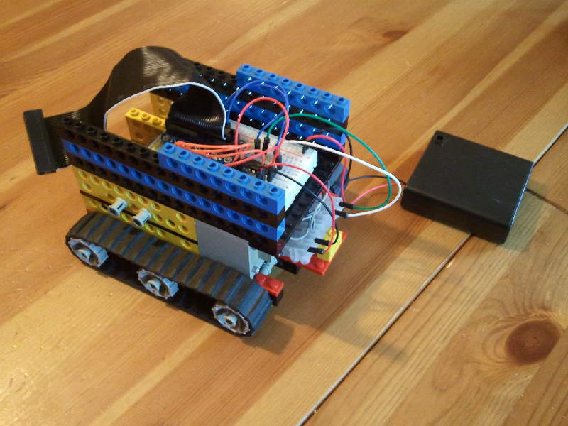
26. This is my battery box holder. Yours will almost certainly have to be different, as the chances of us picking the same battery boxes are pretty small, and it'll be totally different to house batteries for the 9v system.
Again, there's absolutely no benefit to using studded beams here. Regular Lego or studless beams would have worked just as well.
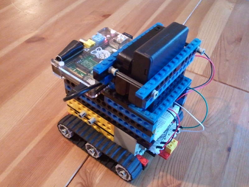
27. The finished article, with two battery boxes. The smaller one is a Portapow Premium 3xAA USB battery pack - essentially an emergency phone charger. The larger battery box is just a straightforward 4xAA battery box with a switch, you can buy these for two or three quid from eBay, Maplin, RS, Farnell etc.
Each AA gives 1.5 volts, why four AA batteries to get 4.5v for the motors? The L293D motor controller microchip, on the breadboard, has a loss of around 1-2 volts, so to get 4.5v output, I need to have 4x1.5 = 6v input.
More about power and wiring up the breadboard in the next section.
Public Domain - Andrew Oakley - 2013-09-17